

Architectural millwork installation is ready when the team can explain how a fixed assembly is supported, located, serviced, finished and finally closed—without the last panel hiding an unresolved interface. That requires more than finished components and an available room. It requires an installation topology: a support root, a control datum, a dependency order, approved places for adjustment, a future access path and a deliberate final closure piece.
Consider a reception counter whose final face panel aligns perfectly. If that panel conceals unverified anchors, traps an electrical access panel or leaves no route to adjust the stone interface, visual completion has arrived before technical completion. The failure began earlier, when the team treated the assembly as a collection of pieces instead of a sequence of closures.

Map the installation topology before site work begins
An installation topology is a one-page overlay on the coordinated drawing. It answers six questions in the order the site team will encounter them:
- Support root: what verified substrate, frame, blocking or other designed support ultimately carries or restrains the assembly?
- Control datum: which approved line, level, centerline or control face governs the visible composition?
- Dependency order: which components must be present, inspected or connected before another component makes them inaccessible?
- Adaptation zones: where does the approved design permit recorded site variation to be absorbed?
- Access path: what must remain removable or reachable for connection, adjustment, inspection and future maintenance?
- Final closure piece: which component closes the system, and who releases that irreversible step?
This overlay does not redesign the millwork. It makes the installation logic visible. Mark each answer against the current drawing revision and link it to the applicable manufacturer instruction, approved detail, request for information or design-team direction. A blank answer is a hold point, not an invitation for the installer to improvise.
Coordinate five closure lines, not one finished face
A fixed assembly closes several systems at once. Use five closure lines to expose where apparently separate decisions collide.
| Closure line | Question before closure | Evidence to retain |
|---|---|---|
| Geometry | Which datum controls the run, and where is the approved terminal condition? | Verified survey reference, coordinated drawing revision and recorded first assembly |
| Support | Is the designed load and restraint path present, accessible and accepted by the responsible party? | Pre-cover record, instruction reference and required inspection release |
| Services | Are penetrations, connection locations, ventilation and maintenance access coordinated before they disappear? | Service-interface sign-off, access confirmation and approved change record |
| Adjacent finishes | Who owns the joint at stone, metal, glass, ceiling, floor, wall or sealant—and which trade closes first? | Approved junction detail, finish sample or first-condition record |
| Operation | Can doors, drawers, removable panels, equipment and maintenance routes operate in the completed space? | Functional check and identified keys, tools, spares or access method where applicable |
The five-line map is editorial coordination guidance, not a technical standard. A project may add fire, acoustic, structural, waterproofing, security or specialist-system lines. The important rule is that a visually acceptable face cannot release an unverified hidden condition.
Confirm the prerequisites at the assembly, not only at the room
“Room ready” is too broad for fixed millwork. The relevant unit is the assembly footprint plus its working, delivery and access envelope. Before installation, confirm:
- the current approved drawings, schedules, manufacturer instructions and change directions are available at the workface;
- the assembly identity and component coding correspond to the zone and revision;
- the governing datum and site dimensions have been verified by the responsible parties using the project method;
- substrates, supports and required blocking or strapping match the governing design information;
- service locations, access panels, adjacent finishes and trade sequence have a named owner;
- the delivery path and work area protect finished components from uncontrolled handling or exposure;
- required interior environmental conditions and protection measures are established; and
- the first assembly and irreversible closure points have defined review authority.
The official ANSI/AWI 0620-2024 overview describes the current interior finish-carpentry and installation standard shown by AWI, while its general requirements address topics including governing contract documents, manufacturer instructions, supports and interior environmental controls. Whether that standard applies—and which edition, requirements or exceptions govern—depends on the contract. The project team must use its actual documents rather than importing a generic tolerance or condition from this article.
Lock the control datum and terminal condition together
A datum is useful only when the team knows where accumulated variation is allowed to end. If repeated panels are simply set from the nearest wall, a small difference at every module can become a visible problem at a doorway, ceiling feature, stone return or centered fixture.
For each elevation or assembly, record:
- the governing control line or face and the party that established it;
- the reference component from which the sequence begins;
- the joints or reveals that must remain visually consistent under the approved design;
- the terminal edge or closure condition; and
- the approved location where residual site variation may be resolved.
Do not assume that the closest existing wall is the visual authority. A centered lobby feature, a ceiling grid or another coordinated control may govern the composition. Equally, do not move the datum in the field to make one local condition easier. Record the conflict and route it through the project’s design authority.
Keep site adjustment inside an approved adaptation ladder
Site conditions rarely reproduce design geometry perfectly. The control question is not whether variation exists; it is where and how the approved design allows that variation to be resolved. Use a three-level adaptation ladder:
- Designed adjustment: use only the adjustment feature already shown or authorized for that assembly—such as a designated scribe, filler, plinth, shadow condition or adjustable interface—within the project’s stated limits.
- Documented project direction: when the measured condition is outside the designed adjustment, obtain a revised detail, approved field instruction or other direction from the responsible authority before modification.
- Stop and recover: quarantine the affected component or zone when the proposed action could alter structure, appearance, durability, service access, certification, finish integrity or another trade’s work.
Examples in this ladder name possible design concepts, not permissions. Never cut, pack, drill, scribe, refinish, relocate a fixing or alter a service interface merely because a similar detail worked elsewhere. The current approved documents and qualified project parties determine what is allowed.
Sequence the work by what will become hidden
A component list tells the installer what exists; a dependency order tells the project what cannot safely be concealed yet. Start with the last closure piece and work backward:
- What inspection, connection or adjustment becomes impossible when this piece is installed?
- Which evidence proves that hidden work is complete?
- Which adjacent trade needs access before closure?
- Which removable feature must still work after the visible face is complete?
- Who has authority to release closure?
The resulting order may differ from the packing list. A visually prominent face panel might be installed late because it conceals service connections. A removable access panel may be fitted and tested early but protected and finally secured later. Sequenced packaging and project coding can support the order, but the site team still has to connect each package to the installation topology.
Capture three witness moments before evidence disappears
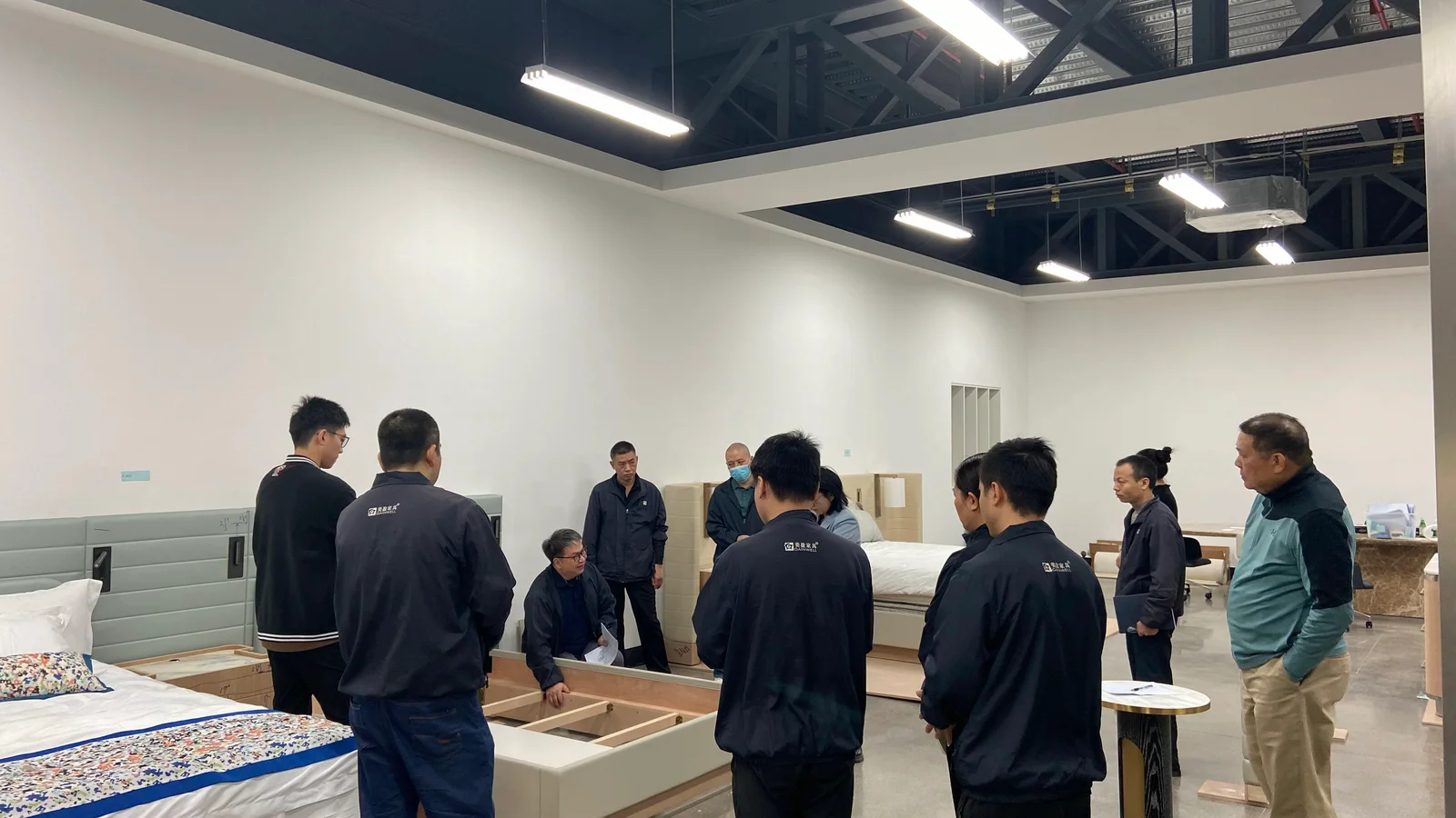
Long photographic reports often show completed surfaces while missing the conditions that caused later disputes. A more useful record is organized around three witness moments:
- Exposed: before concealment, show the identified assembly, support condition, relevant service interface, drawing reference and any required inspection status.
- Aligned: before irreversible fixing or finish closure, show the datum, dry-fit or first-condition result, terminal relationship and approved adjustment location.
- Closed: after completion, show the finished junctions, required operation, retained access and protection or handover status.
Each record should identify the zone, assembly code, date, revision and responsible reviewer. The point is not the number of photographs. The point is whether a later reviewer can connect the finished face to the hidden condition and the instruction that authorized it.
Worked example: close a reception counter without closing the wrong thing
Imagine a lobby reception counter with a millwork carcass, decorative face, stone top, metal trim, integrated equipment and service access. This is an illustrative coordination example, not a construction detail.
- Root and datum: the coordinated drawing identifies the designed support and the approved centerline or control face. The site team verifies those references before distributing modules.
- Dependency chain: the counter body establishes the geometry; services and equipment interfaces are checked while open; the stone and metal junctions are reviewed against the same control; the decorative closure follows only after access has been proven.
- Adaptation location: the approved drawing identifies where measured floor or wall variation may be resolved. No other visible module becomes an informal adjustment zone.
- Witness moment: the team records support and service conditions while exposed, the assembled control faces before irreversible closure and the final operational/access result.
- Last-piece release: the named reviewer confirms that required connections, inspections and future access are complete before the final face or closure panel is secured.
If the service connection conflicts with a support, the installer does not choose which system to move. The zone remains open, the condition is documented and the responsible design and trade parties issue direction. That short pause protects both systems from an undocumented field compromise.
Route every mismatch to one of four outcomes
A mismatch log becomes useful when it ends in a controlled outcome rather than a collection of photographs. Classify each observed condition into one of four routes:
| Outcome | Use when | Required record before continuation |
|---|---|---|
| Accept as documented | The condition matches the governing documents and approved installation method | Verification reference and normal progress record |
| Resolve within designed adjustment | The condition fits a clearly authorized adaptation zone and limit | Measured condition, applicable detail and resulting check |
| Obtain project direction | The condition needs a responsible party to select or revise a solution | RFI, instruction or approved coordinated detail |
| Hold and recover | The condition could compromise hidden support, services, safety, appearance, access or another system | Isolated scope, nonconformance route and formal release |
Do not use “installer to verify” as the final outcome when the installer lacks design authority. Verification discovers the condition; it does not automatically transfer responsibility for redesign.
Protect environmental and finish conditions through closure
Installation readiness is not permanent. Interior conditions, wet work, dust, uncontrolled access or adjacent-trade activity can change after a morning release. The project should define how conditions are checked, who records exceptions and when a previously released area returns to hold.
Use material- and project-specific requirements for conditioning, storage, handling, installation and protection. Do not adopt a universal temperature, humidity, moisture or waiting-period value from an unrelated project. If the governing documents conflict or a condition moves outside the approved envelope, record it and obtain direction before irreversible work.
Protection also needs an exit rule. Temporary film, board or wrapping should not conceal damage, trap an unsuitable condition or block required access. Identify who maintains protection, who may remove it for inspection and when the completed work changes custody.

Qualify an installation company through artifacts
A claim of “expert installation” is difficult to compare. Ask each proposed installer or installation team for evidence tied to the actual assembly and project controls.
| Question | Useful evidence | Warning sign |
|---|---|---|
| How will revisions reach the workface? | Drawing register, superseded-document control and briefing record | Installers rely on personal message threads or unmarked prints |
| How will site geometry be related to the design? | Survey method, datum record and named responsibility boundary | Each installer starts from the nearest finished surface |
| How will manufacturer instructions be reviewed? | Assembly-specific instruction register and pre-task review | Generic experience is presented as permission to modify |
| How will hidden work be released? | Witness-point checklist with zone, assembly and reviewer fields | Only finished-face photographs are proposed |
| How will mismatches be controlled? | RFI, nonconformance and quarantine route with response authority | Field solutions are agreed verbally and recorded later |
| How will completed work be handed over? | Operation checks, access record, protection status and defect closure | Completion means only that visible components are present |
Also verify relevant trade competence, supervision, insurance, safety systems, labor obligations, permits and local requirements through the qualified project parties. Those requirements vary by jurisdiction and contract; this article does not certify an installer.
Define completion as a closure record
A millwork assembly is complete when its required closures are evidenced, not simply when every visible component is fitted. A compact closure record should show:
- assembly and zone identity;
- approved drawing and instruction revisions;
- datum and terminal-condition confirmation;
- hidden support and service release references;
- site adaptations and their authority;
- finished-junction and operational checks;
- retained access, keys, tools or removable-component information where applicable;
- open defects, protection status and custody; and
- the reviewer who released final closure.
The completion state is therefore specific: the representative assembly has passed all three witness moments, each of the five closure lines has evidence or an accepted exception, no unauthorized adaptation remains and the access path still works. Only then should the project release repetition based on that condition.
Use manufacturer input without blurring project responsibility
Gainwell’s current architectural millwork page asks project teams for design drawings, site dimensions, materials and finishes, installation programme and interface information. Its capabilities overview describes technical development, project coordination, quality control, packaging, coding and installation-support context. These inputs can help make the installation topology traceable from drawing to packaged component.
They do not replace the architect, engineers, main contractor, specialist trades, authority requirements or the live contract. Exact scope—including surveys, shop drawings, fixing design, site supervision, labor, testing, protection and closeout evidence—must be confirmed for the individual project.
If you are preparing a fixed millwork package, send the current drawings, site dimensions, material schedule, interface list, destination, programme and proposed installation responsibility through the Gainwell project enquiry page. Ask for a project-specific review of the assembly boundaries and information still needed before quotation or installation planning.