What Is Architectural Millwork? Scope, Examples and Project Interfaces
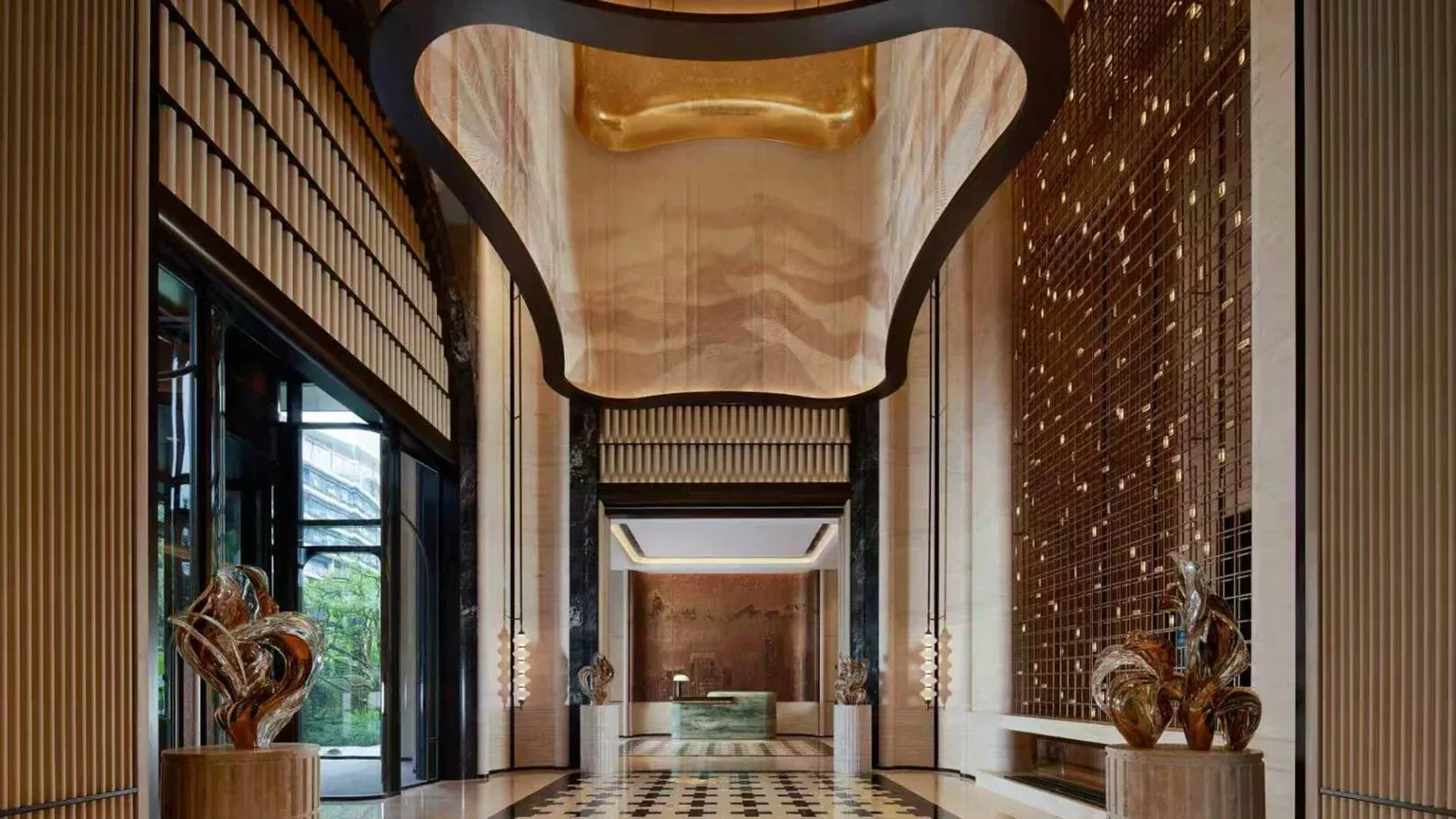
Architectural millwork is architectural woodwork and related shop-fabricated interior assemblies developed for a building setting. In a hotel, it may appear as wall paneling, decorative trim, reception or bar fronts, integrated wardrobes, fixed cabinetry, screens, feature surrounds or other elements that connect design intent to the architecture.
The label is a starting point, not a complete scope. It does not prove that an assembly is solid wood, fully custom, nonstructural, supplied under one contract or installed by its fabricator. Drawings, specifications, schedules and appointments must identify the actual components and responsibilities.
To understand millwork, read the room as connected assemblies. Ask what is being fabricated, what it touches, which information controls the fit and which evidence allows the next commitment.
Read the room before naming the package
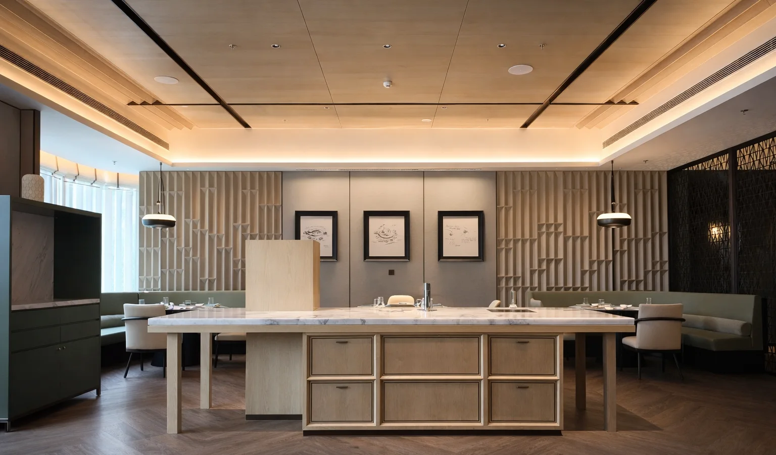
In the pictured interior, several visible elements could involve architectural millwork: paneled surfaces, integrated shelving, the central cabinet-and-counter assembly and fixed seating surrounds. Yet the space also contains loose tables and chairs, upholstery, lighting, floor and ceiling work, decorative surfaces and possible service interfaces.
Calling the entire scene “millwork” would hide those boundaries. A better room-reading exercise is to identify each functional assembly, then separate its components. For example, a host or service station might include a wood-based carcass, doors and drawers, a specialist worktop, hardware, power, equipment, floor fixing and operating contents. One party may coordinate the assembly without supplying every component.
This distinction matters early. It determines which drawings are needed, who supplies dimensional data, which items are priced together and whose approval releases fabrication.
What does architectural millwork mean in current project language?
The Architectural Woodwork Institute’s glossary directs “millwork” to “architectural woodwork.” AWI also publishes separate standards areas for millwork and wood trim, paneling, casework, materials, submittals and installation. That structure shows why a single everyday term can sit above several more precise technical scopes.
For a hospitality project, a useful working definition is:
Architectural millwork is architecturally coordinated woodwork, trim or related shop-fabricated interior assemblies made or selected for a specific building context.
“Architecturally coordinated” is the important condition. The assembly relates to walls, floors, ceilings, openings, services, adjacent finishes or fixed equipment. A standard moulding can qualify when specified as architectural work. A highly customized table may remain loose furniture if it does not form part of the fixed interior package.
Use four boundaries instead of one product label
| Boundary | Question | What the answer controls |
|---|---|---|
| Assembly | What complete functional element is the project trying to create? | Item identity, component breakdown and coordinating party |
| Architecture | Which walls, floors, ceilings, openings, services or fixed conditions does it touch? | Survey, clearances, supports, transitions and sequence |
| Information | Which drawings, dimensions, equipment data, material references and approvals govern it? | Design responsibility, submittals and release status |
| Commercial scope | Who details, supplies, installs, connects, protects and accepts each component? | Pricing boundary, procurement route and handover responsibility |
If all four answers are clear, the team can use whichever terminology its contract adopts. If one answer is missing, changing the label from “millwork” to “joinery” or “fixed furniture” will not close the gap.
How is millwork different from casework, fixed furniture and carpentry?
The terms overlap in ordinary use, and regional language differs. Use them to organize the work, then let the contract documents establish the final boundaries.
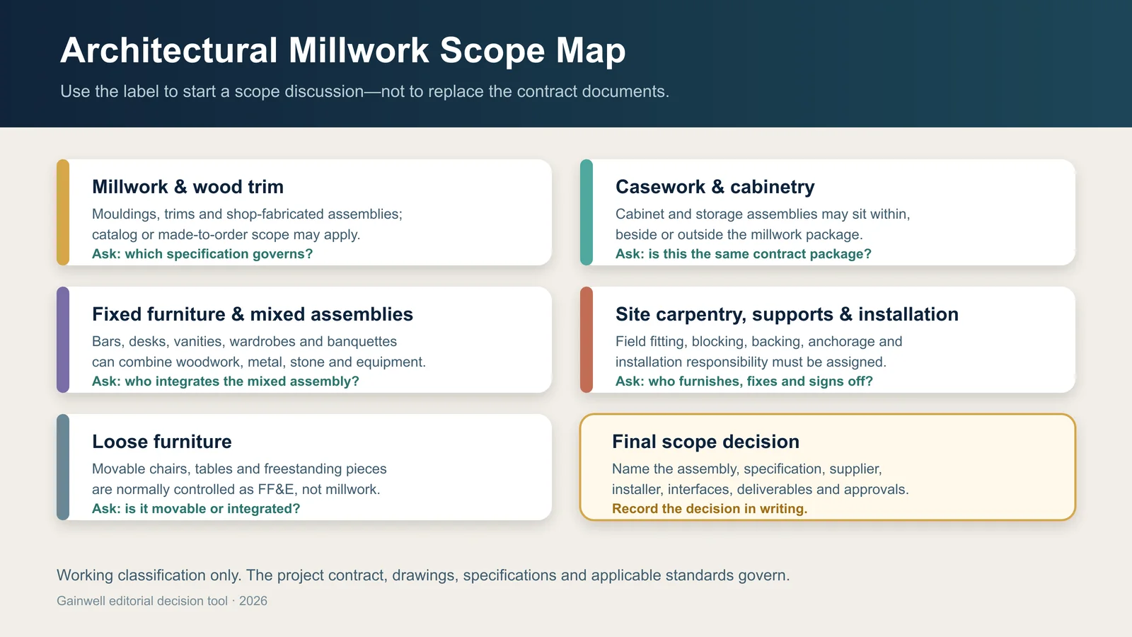
| Term | Useful working meaning | Do not assume |
|---|---|---|
| Millwork and wood trim | Profiles, trim and shop-fabricated woodwork assemblies associated with the architecture | That every item is one-off or that installation is included |
| Architectural casework | Cabinet and storage work controlled through a casework scope, often including boxes, doors, drawers, shelves and hardware | That it is always standard, always separate from millwork or owned by the same installer |
| Fixed furniture | A project category for furniture-like elements secured to or designed as part of the space | That anchorage alone identifies the technical specification or supplier |
| Joinery | A regional or project term often covering fabricated woodwork, cabinetry and fitted interiors | That its boundary is identical in every market |
| Site carpentry | On-site work such as grounds, blocking, furring, fitting, scribing, trimming or installation where assigned | That it is included with shop fabrication |
| Loose FF&E | Movable scheduled items such as chairs, tables and freestanding furniture | That a movable item has no power, anchorage, assembly or building interface |
AWI publishes architectural wood casework as a distinct standards scope, and its public scope identifies exclusions including installation and certain building-integrated supports. That is not a universal contracting rule. It is a useful reminder to name supply, support and installation instead of assuming that one technical category includes them all.
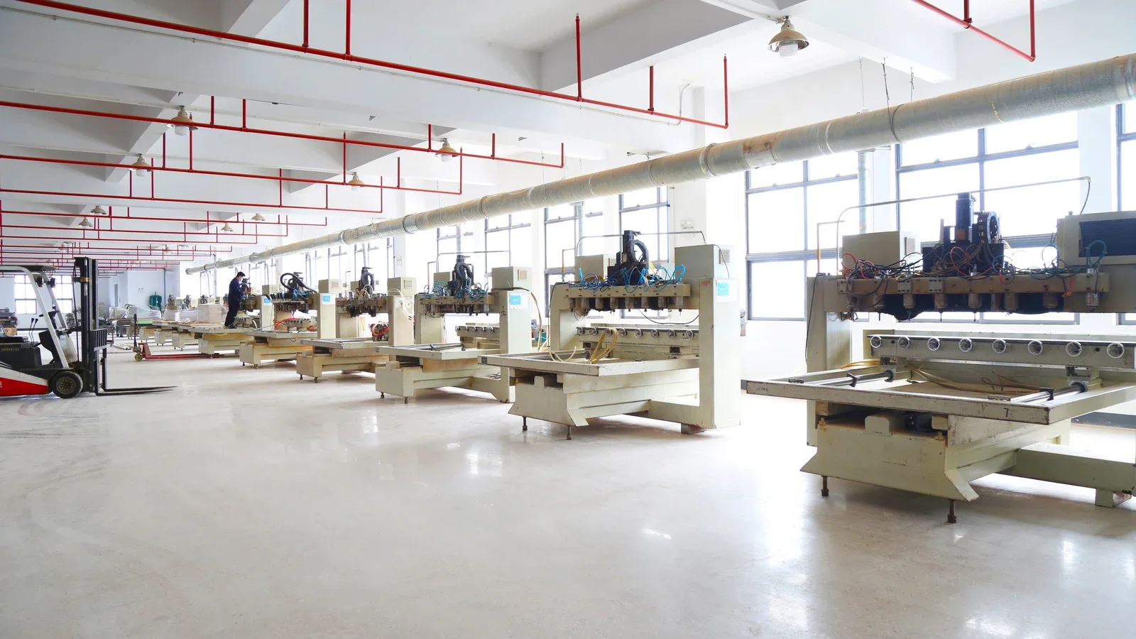
Where does architectural millwork appear in hotels?
Look for assemblies where a fixed interior function, repeated detail or visual language must meet a specific space.
| Hotel zone | Possible millwork-led assembly | Components or interfaces to separate |
|---|---|---|
| Lobby | Reception or concierge desk, feature wall, portal or screen | Data, power, security equipment, accessible service position, stone, metal, lighting and floor fixing |
| Guestroom | Integrated wardrobe wall, minibar enclosure, vanity or headboard feature | Appliance model, ventilation, safe, power, plumbing, mirror, lighting, skirting and field dimensions |
| Restaurant or bar | Host station, back bar, counter front, waiter station or fixed banquette | Food-service equipment, worktop, sink, drainage, power, cleaning access, upholstery and operating storage |
| Corridor or lift lobby | Wall paneling, door surrounds, niches, trims or decorative screens | Doors and hardware, access panels, movement joints, adjacent finishes, impact zones and project requirements |
| Meeting or entertainment space | Media wall, display cabinet, host desk or equipment enclosure | AV equipment, cable routes, ventilation, access, replacement route and acoustical elements |
The examples do not classify every hotel item. A minibar may be a freestanding casegood in one project and an integrated millwork assembly in another. A banquette may combine a fixed base, upholstery, decorative screen and loose tables. Decompose the actual design.
Architectural millwork is not a synonym for solid wood
Visible timber does not prove the internal build-up, and a wood-based assembly may carry non-wood finishes or components. Architectural woodwork can use lumber, veneer, wood-based cores and other specified surfaces; integrated hospitality assemblies can also coordinate metal, glass, stone-like surfaces, upholstery, hardware and equipment.
Describe materials by component. Separate the core or substrate, visible face, edges, backing, frame, hardware, protective finish and specialist inserts. Record grain direction, matching intent, color and sheen references, exposed ends and transitions where they matter. Do not approve hidden construction from a photograph or use a finish name as a complete material specification.
Material suitability, emissions, fire behavior, moisture exposure, structural support, hygiene, accessibility and other regulated or performance requirements must be defined and reviewed for the actual project, market and application.
Decompose the assembly before requesting a price
A millwork-led assembly often has seven layers of responsibility:
- Purpose: the guest, staff or operational function the assembly must perform.
- Primary build-up: carcass, frame, panels, doors, drawers, shelves, trim or decorative faces.
- Specialist components: worktops, glass, metal, upholstery, signage, lighting, appliances or equipment.
- Building interface: floor, wall, ceiling, opening, substrate, support, fixing and transition conditions.
- Services: power, data, plumbing, ventilation, controls and maintenance access where applicable.
- Site work: measurement, setting out, unloading, distribution, installation, connection, protection and making good.
- Evidence: drawings, samples, mock-ups, inspection points, accepted exceptions and closeout records.
This decomposition makes proposals comparable. One supplier can price a cabinet body and doors while another includes the worktop, survey and installation. The totals should not be compared until the seven layers are aligned or the differences are visible.
Use interface density to decide how early coordination must start
Interface density is a simple planning signal: count the independent conditions or parties that can change the assembly’s fit, function, appearance or release. It is not a risk score or engineering calculation.
A run of decorative trim may have a few interfaces: profile, substrate, adjacent finish, corner condition and installation. A hotel bar can have many: floor levels, worktop, metalwork, equipment, plumbing, power, ventilation, lighting, storage, access panels, staff workflow and protection. The bar needs earlier component data, more detailed sections and a clearer responsibility map even if both objects are called millwork.
Escalate coordination when an assembly:
- touches several trades or specialist suppliers;
- contains equipment that may change model or size;
- repeats across many rooms or zones;
- depends on field dimensions that are not yet measurable;
- has concealed access, support or service requirements;
- creates a visually continuous surface across separately supplied components.
What information turns a concept into buildable millwork?
Design-intent drawings can show appearance and location without resolving fabrication. Buildable information normally develops through coordinated plans, elevations and sections; item and location codes; dimensions and datum status; component build-ups; joints, reveals and scribes; materials and finish references; hardware; specialist-component data; services and access; support and fixing concepts; quantity; and revision status.
The AWI 100 submittals scope addresses shop drawings, material data, samples and product data as communication for architectural woodwork and related finishes. A project still needs to state who supplies each input, who reviews it, what the review covers and which record authorizes fabrication.
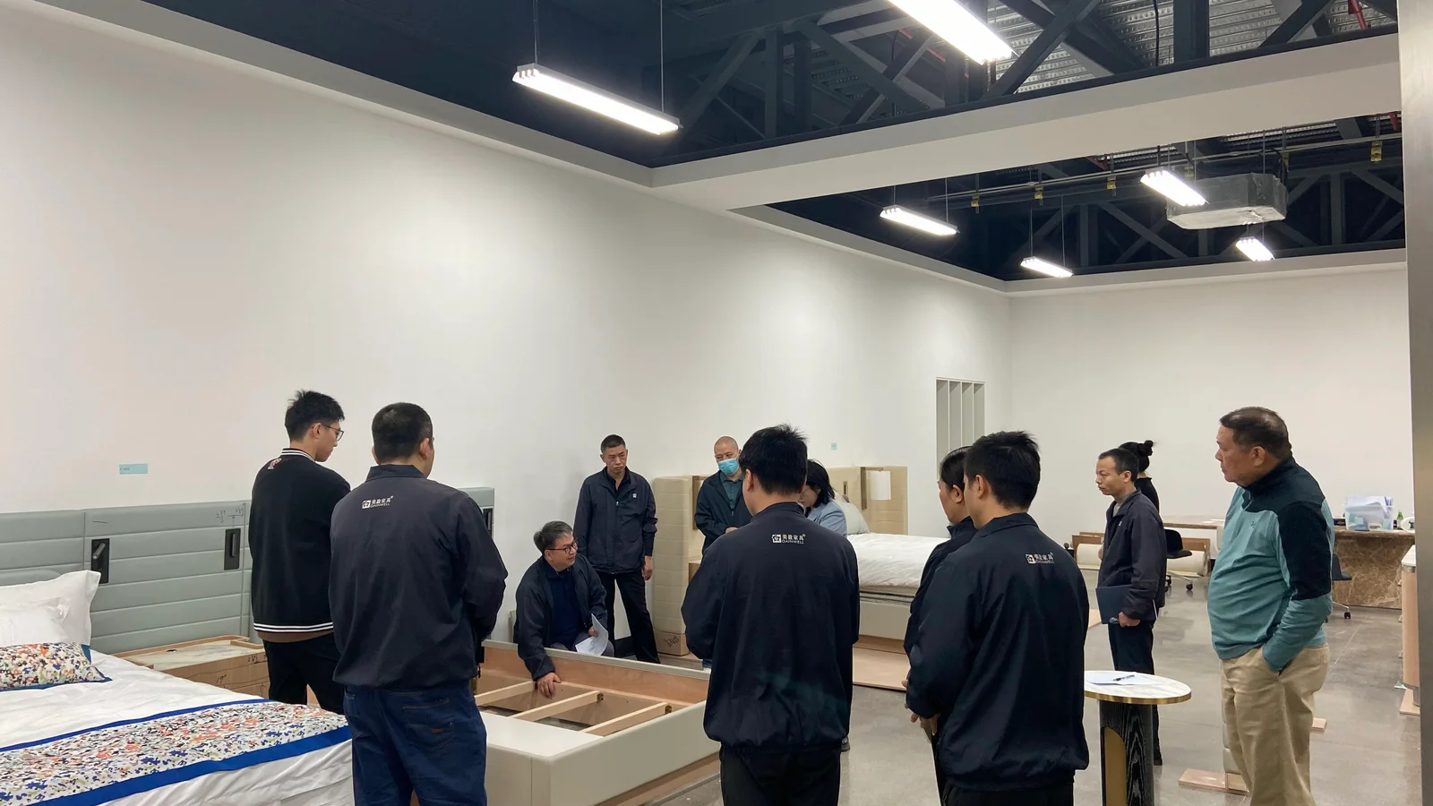
Gainwell’s current capabilities workflow describes shop drawings with dimensions, sections and interfaces, together with material coordination and prototypes or mock-ups. These are company-level capabilities. A live proposal must confirm the survey, design, engineering, samples, tests, installation and approval services included for the exact package.
Match approval evidence to the decision
| Evidence | Useful decision | What it does not automatically approve |
|---|---|---|
| Material or finish sample | Visible surface, color, sheen, grain or a bounded finish range | Dimensions, assembly, hardware, fit or installed appearance |
| Shop drawing | Recorded geometry, build-up, joints, interfaces and current coordination assumptions | Unshown conditions, material performance or every site dimension |
| Detail mock-up | A representative junction, edge, reveal, transition or workmanship reference | The complete room, concealed construction or future production consistency |
| Full assembly or room mock-up | Scale, relationships, operation, access and visual integration within the reviewed scope | Unreviewed performance, all locations or automatic fabrication release |
| Fabrication release record | The named revision, quantity, approved references and authorized exceptions allowed to proceed | Site readiness, installation acceptance or closeout |
Write the boundary of every approval beside the record. “Approved” without a reviewed object, revision, attributes and authority is too vague to control repetition.
Create a millwork assembly passport
Use one concise record for each repeated, expensive, visually critical or interface-heavy assembly. The passport should not replace the drawings; it should connect them.
- Assembly ID and name: one stable code and plain-language description.
- Function and locations: who uses it and where it repeats.
- Controlling documents: current plan, elevation, section, specification and schedule references.
- Component map: primary woodwork, specialist components, equipment and operating contents.
- Material references: build-ups, finishes, approved samples and variable ranges.
- Geometry status: controlled design dimensions, field-verified dimensions and approved adjustment zones.
- Interface register: substrate, support, services, adjacent finishes, access and sequence.
- Responsibility: who details, provides data, supplies, installs, connects, protects and accepts.
- Submittal and approval route: required evidence, reviewer, authority and current status.
- Quantity and release: approved quantity, revision, exceptions and release record.
- Delivery and handover: module or package code, destination, installation owner and accepted records.
- Open decisions: owner, due date and consequence if unresolved.
The passport gives designers, procurement teams, fabricators, contractors and operators one common index. A change to an appliance, worktop, wall build-up or finish can then be traced to every affected drawing and responsibility.
What is not automatically included in a millwork package?
Do not assume the package includes field survey, structural or concealed support, grounds or blocking, building-service design, specialist worktops, metal, glass, upholstery, equipment, connections, fire stopping, delivery beyond an agreed point, installation, sealants, protection, cleaning, making good, testing or as-built records. Any of these can be included—but only when the live scope says so.
Likewise, do not exclude coordination just because a component is supplied by another party. If a stone top, appliance or light affects the millwork geometry, the assembly needs current data, a handoff condition and a named decision owner.
Where does Gainwell fit in the project?
Gainwell’s current architectural millwork and fixed-furniture category presents hospitality examples including reception desks, bar counters, feature walls, vanities, integrated wardrobe walls, decorative screens and fixed banquettes. The page serves commercial category and project-enquiry intent; this guide serves the earlier definition and scope task.
Before requesting a review, prepare the assembly passports, current drawings, location and quantity schedule, material direction, interface register, dimension status, required evidence, destination and requested responsibilities. Share the architectural millwork scope with Gainwell so the team can confirm which assemblies, technical inputs and services fit the live proposal.